Harmonic & Power Factor
Power quality is a significant concern for today's manufacturing and power generation facilities. Finding the right solution for unbalanced loads is important. Two major power quality issues are harmonic distortion and reactive power generated by a low power factor.
Devices such as variable frequency drives, servo drives, LED light drivers and other devices that rectify AC to DC can generate harmonic distortion. It is important to limit the distortion under a certain level in order to reduce effects on other equipment in a facility.
Reactive power, which may be capacitive or inductive, causes the current waveform to change phases respective to the voltage waveform. The capacitance causes the current to lead and the inductance causes lag.
In power transmission, due to the fact that most loads are inductive, there is more reactive power resulting in extra current being supplied. This leads to power loss and high temperatures with additional cost to the operator. For this reason industries are charged extra if they have a low power factor.
Harmonic Theory
In a sinusoidal wave it is important to understand when harmonics are generated. The electrical network provides a sinusoidal voltage and the load absorbs a certain current which depends on the impedance of the load itself.
If the response is linear, the relationship between voltage and current is constant. In a resistive load for example, the current wave shape will be identical to the shape of the voltage wave that is sinusoidal and therefore without distortion.
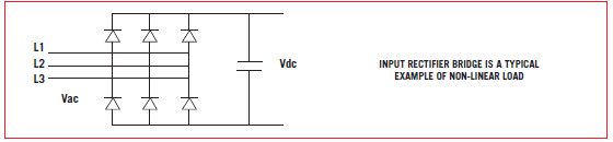
If the load response is not linear, the current waveform will not follow the voltage waveform but will depend on the ratio between voltage and current at each instant. This will therefore result in a non-sinusoidal waveform.
A typical example of a non-linear load is represented by the input rectifier bridge built inside drives.
Harmonic Rating
THD and TDD parameters are used to evaluate harmonic content.
THD or Total Harmonic Distortion is expressed as a percentage and is calculated according to the following formula:
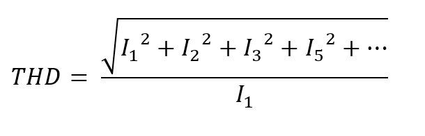
Where I1 represents the current at that moment, I2, I3... represent the harmonic currents at that moment.
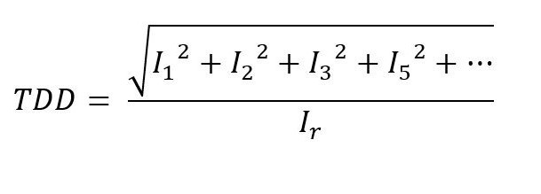
TDD or Total Demand Distortion is the same as calculating the THD but instead of referring to the fundamental current, it refers to the current Ir which is the rated current of a full load.
The THD is measured by a percentage instant value and has no real indication of the amount of harmonic distortion without knowing the load current absorbed at that particular moment.
The TDD refers to the rated current and gives an immediate indication of the harmonic distortion, as the rated current is a known datum. THD and TDD coincide with the rated current.
Power Factor
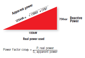
Power factor is defined as a ratio between real power and apparent power in the circuit. The measured value of power factor is the interval between -1 and 1. A power factor less than one indicates that the voltage and current waveforms are not in phase. A negative power factor occurs when the load generated power flows back to the source. Typical examples of low power factor are:
- Linear loads: induction motors
- Non-linear loads: rectifiers
In a typical electric power system, a load with low power factor draws more current than a load with higher power factor. Higher current increases energy loss, requiring a larger cable wire and additional solution. For this reason, electrical utilities usually charge a higher price to facilities with low power factor.
Problems Generated by Harmonics and Displacement Power Factor
Both harmonic distortion and displacement power cause the following problems in an installation:
- Oversizing of power cables, transformers and generators to support higher currents due to reactive energy
- Voltage harmonic distortion due to an unbalanced load propagated to other loads in the installation
- Disruptive resonance with other reactive components on the same power line
- Higher utility costs due to kVAR returning to the mains
- Communication interference
- Energy loss
Harmonic Solutions
The Enerdoor devices used to reduce current harmonic distortion are:
- DC chokes
- Line reactors
- Passive or active harmonic filter
Below are typical examples of a non- linear load with current THD % versus cost.
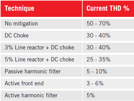
Enerdoor has developed a series of line reactors and passive and active harmonic filters to meet any type of requirements in terms of harmonic reduction and cost. Line reactors and passive harmonic filters are recommended for single drive applications and sized by the total current.
As an alternative, the active harmonic filter works in parallel and compensates current for single or multiple load applications operating under varied loads. They may be used for single applications or an entire facility.
Power Factor Solution
The most common solution to compensate power factor correction is a capacitor bank. Capacitance compensates for inductive loads by floating the power factor close to 1. The Enerdoor FINSVG static var generator is a superior alternative to the capacitor bank. It compensates the power factor using an Insulated Gate Bipolar Transistor (IGBT) instead of traditional capacitor banks. This superior technology is a modular system which may be installed in parallel to the main line. Major advantages of a static var generator vs traditional capacitor banks include:
- Not influenced by harmonic resonance
- Compensates both inductive and capacitive reactive power
- System is active. Voltage from the grid has no influence on the compensation capacity
- Very fast response